
This small lidar-based distance sensor detects the presence of objects within 50 cm (20″). It has a single digital output that drives low when an object is being detected; otherwise, it is high. It works over an input voltage range of 3.0V to 5.5V, and the 0.1″ pin spacing makes it easy to use with standard solderless breadboards and 0.1″ perfboards.
It is one of a family of sensors available with differing detection distances as well as a choice between a digital or pulse width output. Each has the same dimensions and pinout.
|
Digital output
(does not provide distance measurement)
|
|||||
| Sensor | Maximum range1 |
Minimum range |
Minimum update rate |
Jumper settings (4321) |
PCB ID |
|---|---|---|---|---|---|
| #4050: Digital output, 5cm | 5 cm | < 5 mm | 145 Hz | 0000 | irs16a |
| #4052: Digital output, 10cm | 10 cm | < 5 mm | 115 Hz | 0010 | |
| #4054: Digital output, 15cm | 15 cm | < 5 mm | 95 Hz | 0100 | |
| #4066: Digital output, 25cm | 25 cm | < 1 mm | 100 Hz | 0000 | irs17a |
| #4067: Digital output, 50cm | 50 cm | < 1 mm | 100 Hz | 0001 | |
| #4069: Digital output, 100cm | 100 cm | < 1 mm | 100 Hz | 0011 | |
| #4077: Digital output, 200cm | 200 cm | < 1 mm | 30 Hz | 1011 | |
| Pulse width output (provides distance measurement) |
||||||
| Sensor | Maximum range1 |
Minimum range2 |
Resolution | Minimum update rate |
Jumper settings (4321) |
PCB ID |
|---|---|---|---|---|---|---|
| #4064: Pulse width output, 50cm max | ~50 cm | 1 cm | 3 mm | 50 Hz | 1110 | irs16a |
| #4071: Pulse width output, 13 |
~130 cm | 4 cm | 1 mm | 100 Hz | 0101 | irs17a |
| #4079: Pulse width output, 300cm max | ~300 cm | 4 cm | 2 mm | 30 Hz | 1101 | |
1. Effective range depends on object reflectivity and ambient lighting conditions
2. Objects closer than the minimum distance can still be detected but the measured distance may be less accurate. The minimum detection range is <5mm for the irs16a boards and <1mm for the irs17a boards
This 50cm digital compact sensor is a great way to quickly detect the presence of nearby objects. As long as the sensor is enabled, it takes continuous distance measurements and uses a single digital output to indicate if it detects an object within its detection range. The output is driven low when the sensor detects an object; otherwise, the output is high.
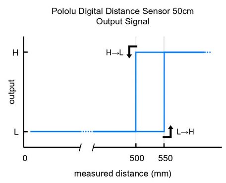
Please note that this sensor will only tell you if there is an object within the detection range along its line of sight, not how far away it is. As shown in the diagram above, there is hysteresis at the maximum range threshold to help ensure a clean transition as objects cross the threshold. The sensor can detect objects to within about 1 mm of the sensor face.
Unlike simpler optical sensors that use the intensity of reflected light to detect objects, this sensor uses a short-range lidar module to precisely measure how long it takes for emitted pulses of infrared, eye-safe laser light to reach the nearest object and be reflected back. This allows the sensor performance to be largely independent of object reflectivity and ambient lighting conditions (though the range can be reduced for extremely low-reflectance objects).
Some example applications include:
- break-beam sensor or photogate alternative
- non-contact bumper or obstacle detector for a robot
- non-contact interface element for activating a device or process
- a counter or timer of objects as they pass by
Specifications
Operating voltage: 3.0V to 5.5V
- Current consumption: 30 mA (typical) when enabled, 0.4 mA when disabled
- Maximum range: 50 cm (10″)
- Minimum range: < 1 mm
- Minimum update rate: 100 Hz (10 ms period)
- Field of view (FOV): 15° typical; can vary with object reflectance and ambient conditions
- Output type: digital signal (low when detecting an object, high otherwise)
- Dimensions: 0.85″ × 0.35″ × 0.122″ (21.6 × 8.9 × 3.1 mm)
- Weight: 0.014 oz (0.4 g)
Using the sensor
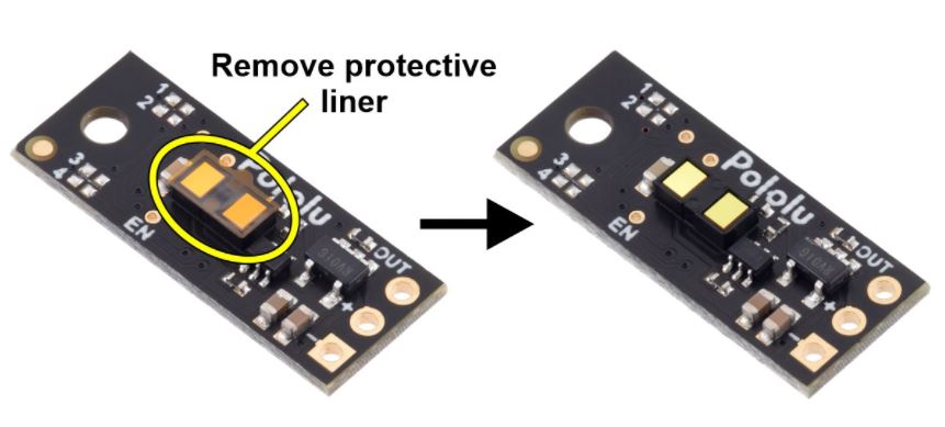
Important note: This product might ship with a protective liner covering the sensor IC. The liner must be removed for proper sensing performance.
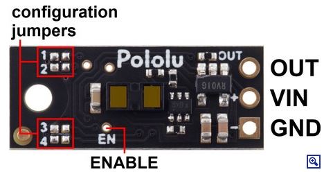
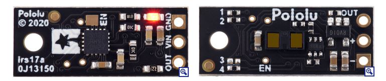
Three connections are necessary to use this module: VIN, GND, and OUT. These pins are accessible through a row of 0.1″-pitch through holes, which work with standard 0.1″ (2.54 mm) male headers and 0.1″ female headers (available separately). The VIN pin should be connected to a 3 V to 5.5 V source, and GND should be connected to 0 volts. The OUT pin drives low (0 V) when an object is being detected and it drives high (to the VIN level) when an object is not being detected. It is weakly pulled high when the sensor is disabled or waiting for its first reading to complete after power-up. A red LED on the back side of the board also lights whenever an object is detected.
The board has an optional ENABLE pin that can be driven low to put it into a low-power state that consumes approximately 0.4 mA. This pin can be accessed through a via or its neighboring surface-mount pad on the back side labeled “EN” on the silkscreen. The ENABLE pin is pulled up to VIN, enabling the sensor by default.
The board has one mounting hole intended for use with #2 or M2 screws.
Jumper settings (irs17a)
The board features four surface-mount configuration jumpers that determine its operation mode. Different versions of the Pololu Digital Distance Sensors ship with the appropriate jumpers pre-populated with 0 Ω resistors. These resistors can be desoldered from the populated spots or solder bridges can be added across the unpopulated spots to convert one sensor version into another. This sensor can be converted into any other irs17a version as listed in the following table. (For more information about how the different output types work, see the product pages for representative versions.)
| Item # | Description | Maximum range* |
Hysteresis | Resolution | Minimum update rate |
Jumper settings (4321) |
|---|---|---|---|---|---|---|
| 2110-688 | Digital output, 25cm | 25 cm | 50 mm | - | 100 Hz | 0000 |
| 2110-689 | Digital output, 50cm | 50 cm | 50 mm | - | 100 Hz | 0001 |
| Digital output, 75cm | 75 cm | 50 mm | - | 100 Hz | 0010 | |
| 2110-690 | Digital output, 100cm | 100 cm | 50 mm | - | 100 Hz | 0011 |
| Digital output, any detect | ~130 cm | - | - | 100 Hz | 0010 | |
| 2110-693 | Pulse width output, 130cm max | ~130 cm | - | 1 mm (= 0.5 µs) |
100 Hz (110 Hz max) |
0101 |
| Digital output,125cm | 125 cm | 50 mm | - | 30 Hz | 1000 | |
| Digital output,150cm | 150 cm | 50 mm | - | 30 Hz | 1001 | |
| Digital output,175cm | 175 cm | 50 mm | - | 30 Hz | 1010 | |
| 2110-691 | Digital output, 200cm | 200 cm | 50 mm | - | 30 Hz | 1011 |
| Digital output, any detect | ~300 cm | - | - | 30 Hz | 1100 | |
| 2110-694 | Pulse width output, 300cm max | ~300 cm | - | 2 mm (= 0.5 µs) |
30 Hz (33 Hz max) |
1101 |
The output graph is a bit different for the versions that use a pulse width to encode the measured distance. The output for these versions is similar to hobby servo control signals and is shown below as a function of time:
