
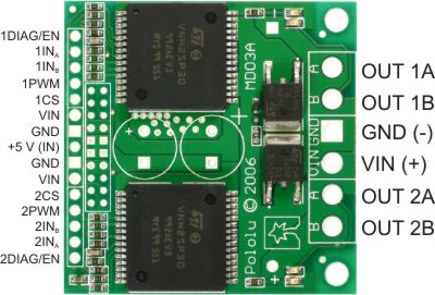


In a typical application, the power connections are made on one end of the board, and the control connections are made on the other end. +5 volts must be supplied to the board through the smaller 0.1"-spaced pins; the input voltage is available at those pins as well, but the connection is not intended for currents exceeding a few amps. The diagnostic pins can be left disconnected if you do not want to monitor the fault conditions of the motor drivers. INA and INB control the direction of each motor, and the PWM pins turns the motors on or off. For the VNH2SP30 version, the current sense (CS) pins will output approximately 0.13 volts per amp of output current.
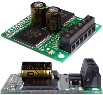
The dual motor driver PCB includes provisions for installing up to three large capacitors to limit disturbances on the main power line. Two 10mm radial capacitors may be mounted between the motor driver ICs, and an axial capacitor may be mounted between the ICs and power connections. It is generally not necessary to use all three capacitors; two radial capacitors are included with each unit. For applications that require a low profile, a single capacitor can be installed on its side as shown in the 'Additional images' gallery.
Please see 1503-007 for further performance data on the VNH3SP30, VNH2SP30 and the IRFR3707Z.
Note: A 15-pin male header, three 2-pin terminal blocks, and two electrolytic capacitors are included but not soldered onto the boards. No printed documentation is shipped with these items.