
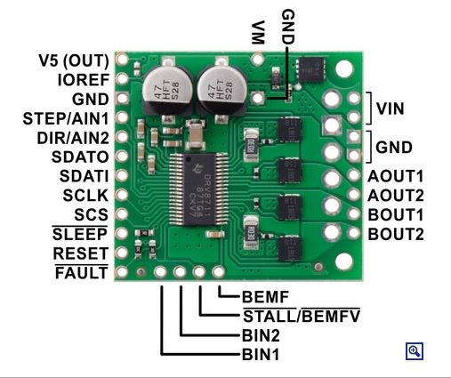
The Pololu High-Power Stepper Motor Driver 36v4 combines the DRV8711 stepper motor driver IC from Texas Instruments with external MOSFETs to enable control of large bipolar stepper motors at operating voltages from 8 V to 50 V. The DRV8711 has many configurable settings, so please see the DRV8711 datasheet for a detailed explanation of its features and how to use them (An Arduino library that simplifies getting started by providing basic functions for configuring and operating the driver is available on the Pololu website).
The driver’s power performance is a function of the external dual H-bridges, which allow the driver to deliver continuous currents up to 4 A per phase without any additional cooling such as heat sinks or forced air flow. (With sufficient additional cooling, the driver can support currents up to around 6 A per phase; see the Power dissipation considerations section below for more information, including important information about using this product safely.)
Key features
- Wide 8 V to 50 V operating voltage range
- High-power: can deliver up to 4 A continuous per phase without extra cooling (6 A max with sufficient additional cooling)
- Highly configurable through SPI interface
- Optional STEP/DIR control pins (stepping can also be controlled through SPI interface alone)
- Nine different step resolutions down to 256 microsteps: full-step, half-step, 1/4-step, 1/8-step, 1/16-step, 1/32-step, 1/64-step, 1/128-step, and 1/256-step
- Adjustable current control lets you set the maximum current output, enabling the use of voltages above your stepper motor’s rated voltage to achieve higher step rates
- Adaptive blanking time, adjustable decay times, and various current decay modes enable the creation of ultra-smooth motion profiles through the SPI interface
- Optional STALL output enables stall detection when microstepping
- Optional BEMF output enables more advanced control and stall detection algorithms based on the back EMF of the stepper motor
- Driver supports alternate operating mode for controlling two brushed DC motors with PWM inputs instead of one bipolar stepper motor with STEP/DIR inputs
- Inputs compatible with 1.8 V, 3.3 V, and 5 V logic
- Digital outputs are all open drain with pull-ups to externally supplied IOREF voltage for use with non-5V systems (IOREF can be connected to neighboring 5V OUT pin for use with 5V systems)
- Under-voltage lockout, over-current protection, short circuit protection, and reverse-voltage protection (up to 40 V)
- Arduino library and example sketches are available that provide basic functions for configuring and operating the driver
As an alternative to this stepper motor driver, our Tic 36v4 USB Multi-Interface High-Power Stepper Motor Controller has similar power characteristics and offers high-level interfaces (USB, TTL serial, I²C, analog voltage, quadrature encoder, and RC hobby servo pulses) that make it easier to use for some applications. The Tic’s configuration software allows you to change many of the driver’s settings over USB, eliminating the need to directly use SPI to configure the DRV8711.
Included hardware
This product ships with all surface-mount components installed as shown in the product picture. However, soldering is required for assembly of the included through-hole parts. The following through-hole parts are included:
- Two 1×12-pin breakaway 0.1″ male header
- Three 2-pin, 3.5 mm terminal blocks (for board power and motor outputs)
- One 0.1″ shorting block (for optionally connecting IOREF to neighboring V5 pin when using this driver in 5 V systems)
The 0.1″ male headers can be broken or cut into smaller pieces as desired and soldered into the smaller through-holes. These headers are compatible with solderless breadboards, 0.1″ female connectors, and our premium and pre-crimped jumper wires. The terminal blocks can be soldered into the larger holes to allow for convenient temporary connections of unterminated power and motor wires (see our short video on terminal block installation). You can also solder your motor leads and other connections directly to the board for the most compact installation.
Open above image in new tab if not clear
At high input voltages (especially above 30 V) and high current limits, the driver’s SPI interface is more likely to be affected by electrical noise from the driver and stepper motor, potentially leading to communication errors. You can reduce this interference with careful wiring and shielding, and you can lower the risk of unexpected behavior by taking appropriate precautions with SPI communication (for example, read and verify configuration settings after writing them, and avoid configuring the driver while the motor outputs are enabled).
Alternatively, consider using our Tic 36v4 USB Multi-Interface High-Power Stepper Motor Controller, which provides high-level interfaces for configuration and control (making direct SPI communication unnecessary).
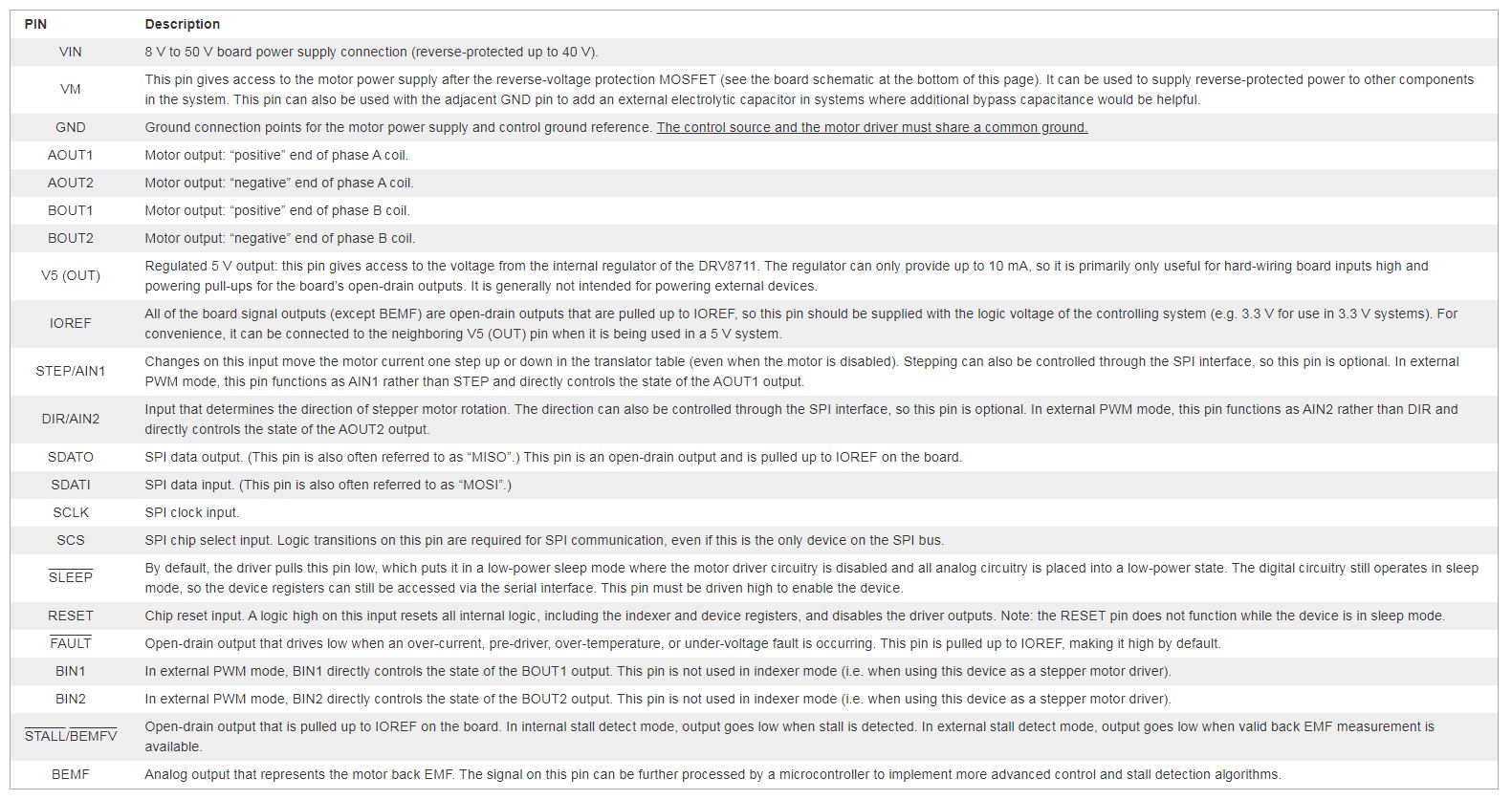
General typical wiring diagram
 Typical wiring diagram for connecting a microcontroller to a Pololu High-Power Stepper Motor Driver 36v4.
While the High-Power Stepper Motor Driver 36v4 allows control of a stepper motor through a simple step and direction interface, it must first be enabled and configured through its SPI interface after each power-up. This means that the controlling microcontroller must be capable of acting as an SPI master (either with an SPI peripheral or software SPI), and it must be connected to the SDATI, SCLK, and SCS pins. While the SDATO and FAULT pins are not required to use this driver, it is generally a good practice to use them to monitor for error conditions.
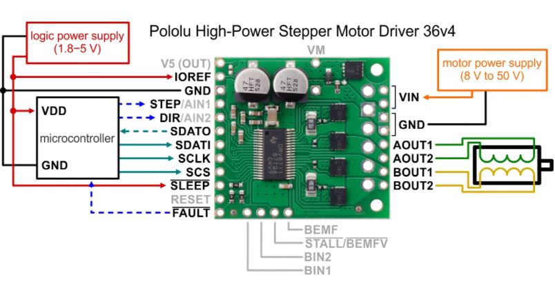
Typical wiring diagram (5V systems only)
 Typical wiring diagram for connecting a microcontroller with a logic voltage of 5 V to a Pololu High-Power Stepper Motor Driver 36v4.
The High-Power Stepper Motor Driver 36v4 has an internal 5 V regulator that can be used to supply IOREF in cases where the board is being used in 5 V systems. We provide a shorting block for connecting V5 to IOREF, or for a more compact connection, you can bridge the surface mount jumper located next to those pins (highlighted in the picture below).
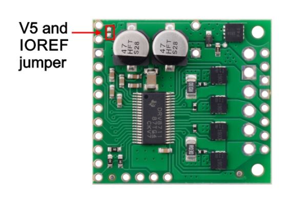 Surface mount jumper for V5 and IOREF pins on the Pololu High-Power Stepper Motor Driver 36v4.
Power dissipation considerations
The High-Power Stepper Motor Driver 36v4 can deliver up to 4 A continuous per phase under typical conditions, but the actual current it can deliver will depend on how well you can keep the module cool. The driver’s printed circuit board is designed to draw heat out of the MOSFETs, but performance can be improved by adding a heat sink or forced air flow. (Conversely, performance will be reduced in applications that limit heat dissipation, such as high ambient temperatures or operation in enclosures.) With sufficient additional cooling, the driver can deliver up to 6 A per phase before exceeding the 1 W power ratings of the 30 mΩ current sense resistors.
The driver’s current limit is set through its SPI interface. You can confirm you have set it correctly by using a multimeter to measure the actual current through one of the coils while the stepper motor is in full step mode and not stepping. The current you measure this way will be approximately 70% of the set limit. Please note that measuring the current draw at the power supply will generally not provide an accurate measure of the coil current. Since the input voltage to the driver can be significantly higher than the coil voltage, the measured current on the power supply can be quite a bit lower than the coil current (the driver and coil basically act like a switching step-down power supply). Also, if the supply voltage is very high compared to what the motor needs to achieve the set current, the duty cycle will be very low, which also leads to significant differences between average and RMS currents.
Warning: This motor driver has no meaningful over-temperature shut-off (while the DRV8711 IC has over-temperature protection, it is the external MOSFETs that will overheat first). An over-temperature condition can cause permanent damage to the motor driver. We strongly recommend you do not increase the current limit setting beyond 4 A (or lower in applications with reduced heat dissipation) unless you can first confirm that the temperature of the MOSFETs will stay under 140°C.
Note: When the driver powers up, the current limit setting defaults to the maximum (~18 A). Make sure you set it to something appropriate for both your stepper motor and the driver before activating the outputs!
This product can get hot enough to burn you long before the chip overheats. Take care when handling this product and other components connected to it.