
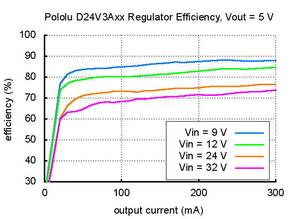
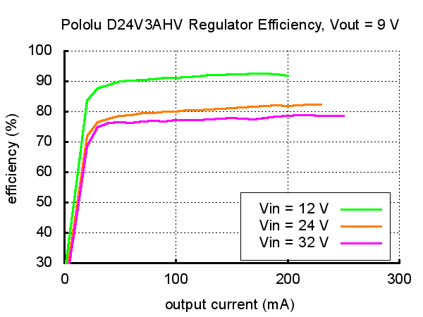
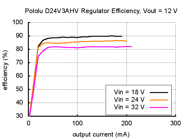


These adjustable buck (step-down) voltage regulators from Pololu generate lower, user-adjustable output voltages from a wide input voltage range of 4.5 to 42 V. They are switching regulators (also called switched-mode power supplies (SMPS) or DC-to-DC converters) and have a typical efficiency of 85%, which is much more efficient than linear voltage regulators, especially when the difference between the input and output voltage is large. The output voltage is set using the board’s trimmer potentiometer, available range of approximately 4 V to 25 V. 300 mA maximum output current.
The regulator has under-voltage and short-circuit protection, and thermal shutdown prevents damage from overheating. The board does not have reverse-voltage protection.
Specifications
- input voltage: 4.5 V to 42 V
- output adjustable from 4 V to 25 V (D24VxAHV)
- maximum output current of 300 mA (D24V3Axx)
- 550 kHz switching frequency
- 2 mA typical no-load quiescent current (20 μA typical quiescent current with SHDN = 0V)
- integrated over-temperature and over-current shutoff
- small size: 0.6" × 0.4" × 0.16" (15 × 10 × 4 mm)
- weight without header pins: 0.03 oz (0.8 g)
Using the Regulator
Connections
The buck regulator has four connections: shutdown (SHDN), input voltage (VIN), ground (GND), and output voltage (VOUT).
The SHDN pin can be driven low (under 0.3 V) to turn off the output and put the board into a low-power state that typically draws 20 μA. The SHDN pin can be driven high (above 2.3 V) to enable the board, or it can be connected to VIN or left disconnected if you want to leave the board permanently enabled.
The input voltage, VIN, should be between 4.5 and 42 V. You should ensure that noise on your input does not exceed the 42 V maximum, and you should be wary of destructive LC spikes (see below for more information).
The output voltage, VOUT, is determined by the trimmer potentiometer position. Setting the output voltage to be higher than the input voltage will not damage the board, but it will produce an oscillating output rather than a clean power rail (see the oscilloscope capture below), so we recommend you avoid setting the output voltage to be higher than the input voltage. The available output voltage range depends on your input voltage, VIN, and the regulator version you have: 2.5 V to 7.5 V (D24VxALV) or 4 V to 25 V (D24VxAHV). The maximum available output current also depends on your regulator version: 300 mA (D24V3Axx) or 600 mA (D24V6Axx). Exceeding the maximum output current can cause the output voltage to drop below its set value.
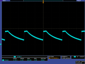  |
| VOUT of the Pololu step-down regulator D24V3ALV when VIN is 5 V and the output voltage setting is higher than 5 V. |
|---|
The four connections are labeled on the back side of the PCB, and they are arranged with a 0.1" spacing along the edge of the board for compatibility with solderless breadboards, connectors, and other prototyping arrangements that use a 0.1" grid. You can solder wires directly to the board or solder in either the 4×1 straight male header strip or the 4×1 right-angle male header strip that is included.
Setting the output voltage
The output voltage can be measured using a multimeter. Turning the potentiometer clockwise increases the output voltage. The output voltage can be affected by a screwdriver touching the potentiometer, so the output measurement should be done with nothing touching the potentiometer. When setting the ouput voltage, note that the buck regulator can only produce voltages lower than the input voltage.
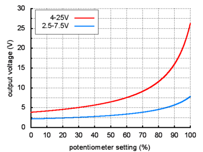 |
| Output voltage settings for the adjustable 2.5-7.5V and 4-25V buck regulators (D24VxAxx). |
|---|
LC Spikes
When connecting voltage to electronic circuits, the initial rush of current can cause voltage spikes that are much higher than the input voltage. If these spikes exceed the regulator’s maximum voltage (42 V), the regulator can be destroyed. In our tests with typical power leads (~30" test clips), input voltages above 20 V caused spikes over 42 V. If you are connecting more than 20 V or your power leads or supply has high inductance, we recommend soldering a 33μF or larger electrolytic capacitor close to the regulator between VIN and GND. The capacitor should be rated for at least 50 V.