Rudder Mixer by Alan Bond
RUDDER MIXER
This PICAXE based project was designed to improve the manoeuvrability of radio controlled model boats powered by twin motors, but of course such a unit is equally applicable to the steering control of tracked vehicles and robots. Improved manoeuvrability is achieved by mixing in the rudder (steering) demand in equal and opposite amounts to each ESC (Electronic Speed Controller). Thus, for example, when turning to port the starboard motor speeds up and the port motor slows down to assist the turning action. If the boat is stationary, rudder application will drive one motor forwards and the other in reverse allowing the boat to literally turn on the spot. A major difference from the commercial rudder mixers I have so far encountered is that the proportion of rudder mixed into the throttle signals can be adjusted by the user - I found that the usual 100% mix resulted in the boat accelerating whilst turning, and I now use about a 60% mix for a decent balance between low speed manoeuvrability and good steering behaviour when under way.
Transistor buffers are used to condition the rudder and throttle signals from the receiver. The output voltage swing of some receivers (especially 2.4Ghz types) has been found to be insufficient to trigger the PICAXE 08M (Schmitt Trigger type) input.
The potentiometer is connected across the 5v supply and its wiper connected to an ADC input of the PICAXE chip, such that its setting may be read and used to set the proportion of rudder mixed into the two throttle outputs.
The following guidance is given for those who wish to try developing the PICAXE program for themselves.
For best input and output resolution (5uSec) operate the chip at 8Mhz. (use 'setfreq m8' command). Thus, word variables must be used to handle the resulting values in the range 200 to 400 (1 to 2 mSec) and the results of the 'gain' calculation.
The value of the throttle channel is read (use 'pulsin' command) and stored for future use. Next the value (0 to 255) of the mix ratio potentiometer is read (use 'readadc' command) and assigned to a gain variable. Then the rudder channel signal is read and the absolute magnitude of its displacement from neutral is determined. This is then multiplied by the gain variable and then divided by 255 to yield the proportion of mix required. This order of calculation must be strictly observed to avoid (massive) truncation errors due to the PICAXE's integer arithmetic. This final result is then added or subtracted to the previously determined throttle channel value depending on which side of neutral the rudder lies to yield one ESC output (use ''pulsout' command) - the inverse logic applies to generate the second ESC output.
Be sure to use the 'min' and 'max' operators to limit the calculations to lie in the range 200 to 400 (1 to 2msec) - eg. full rudder at half speed with 100% mix could otherwise result in a 2.75mSec pulsewidth where the ESC's behaviour is uncertain - it could consider it out of limits and shut down for example.

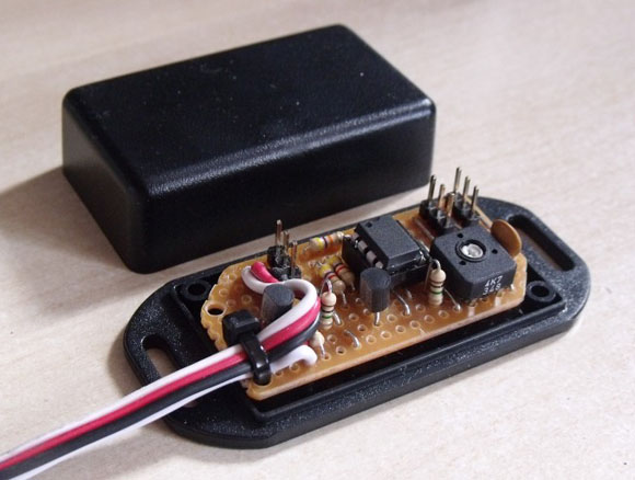
As can be seen from the pictures, the unit is easily constructed on stripboard and has been designed to utilise a small flanged ABS box (Technobots #2800-225) which will afford protection against accidental shorting and/or moisture. 200mm servo leads are soldered in and strain-relieved with tie-wraps to provide the rudder and throttle inputs. The actual rudder servo may be connected to PL1, thereby obviating the requirement for a Y lead. The two ESCs are plugged into PL2 and PL3. No provision has been made for programming the PICAXE chip in situ, so this must be done elsewhere in a slave rig.
All the parts are available from Technobots of course!
PARTS
R1 - resistor 47k #2008-047
R2 - resistor 1M #2009-010
R3 - resistor 4k7 #2007-407
R4 - resistor 47k #2008-047
R5 - resistor 1M #2009-010
R6 - resistor 4k7 #2007-407
C1 - capacitor 100nF ceramic disk - #2013-100
Q1 - transistor BC337-16 #2300-412
Q2 - transistor BC337-16 #2300-412
U1 - integrated circuit PICAXE08M #3803-112 pre-programmed chip
IC Socket for U1 #2700-008
RV1 - preset potentiometer 4K7 #2000-405
PL1 - PCB Header 3 way #2700-081
PL2 - PCB Header 3 way #2700-081
PL3 - PCB Header 3 way #2700-081
2x 200mm servo lead #3601-008
Stripboard 25x64 #2700-105
Box 2800-225