
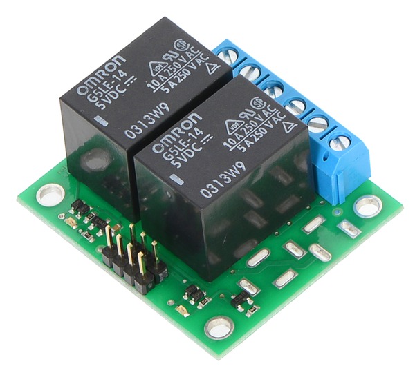


Pololu’s basic 2-channel relay carrier board makes it easy to incorporate a “sugar cube”-style power relay into your electronics project. An integrated MOSFET allows the relay to be controlled with a low-current digital input, and a pair of indicator LEDs show when the relay is activated. The control pins have a 0.1″ spacing compatible with standard solderless breadboards and servo cables, and the switch pins are available for use with 5mm-pitch terminal blocks or 0.2″-spaced pins.
There are 5 variants to this product range, a basic PCB ready populated with the surface mounted components, two partial kits in both 5V and 12V relay versions and fully assembled units again in both 5V and 12V versions.
Note: This item includes the basic carrier PCB along with the Omron G5LE-14-DC12 12V relays, 5.0mm terminal blocks, and 0.1" male headers in straight and right-angle versions. Surface-mount components are pre-assembled on the PCB, but the through-hole components are not installed.
The carrier board routes the relay control pins to 0.1″-spaced pins compatible with standard solderless breadboads and female servo cable connectors. The relay switch pins are routed to a set of large pads intended for use with a 3-pin 5mm-pitch terminal block and a set of smaller pads with a 0.2″ pitch, making them compatible with 0.1″ perfboards.
Advantages over similar products
- Compact layout
- Two LEDs to indicate coil actuation
- Zener diode for fast current decay on relay coil
- Specification of electrical routing clearance rules on relay switch nodes
Using the relay module
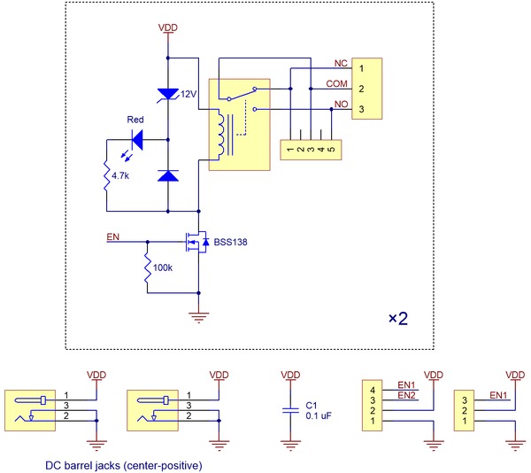
The switch portion of the relay is accessible on one side of the board while the control pins are routed to the other. The relay coil is powered by supplying the appropriate coil voltage for your specific relay across the VDD and GND pins, and it is activated by a digital high control signal on the EN pin. The control signal is fed directly to a BSS138 N-channel MOSFET, which in turn actuates the relay coil when the control voltage exceeds approximately 2.5V (see BSS138 datasheet (92k pdf) for details).
The relay switch terminals COM (common), NO (normally open), and NC (normally closed) are routed on the PCB with a minimum clearance of 60 mils (1.5mm) from other copper. The copper traces are designed to be at least 45 mil (1.1mm) from the board edges, though manufacturing variations in the board edges can make those distances slightly lower.
In most applications, the current and voltage ratings for the module will match the ratings of the relay used. Maximum current, maximum voltage, and life expectancy are interdependent; we therefore recommend careful examination of your relay’s datasheet.
Warning: This product is not designed to or certified for any particular high-voltage safety standard. Working with voltages above 30 V can be extremely dangerous and should only be attempted by qualified individuals with appropriate equipment and protective gear.
Schematic diagram
Click on thumbnail image above
Size
46 x 38mm x 23mm high